System diagrams
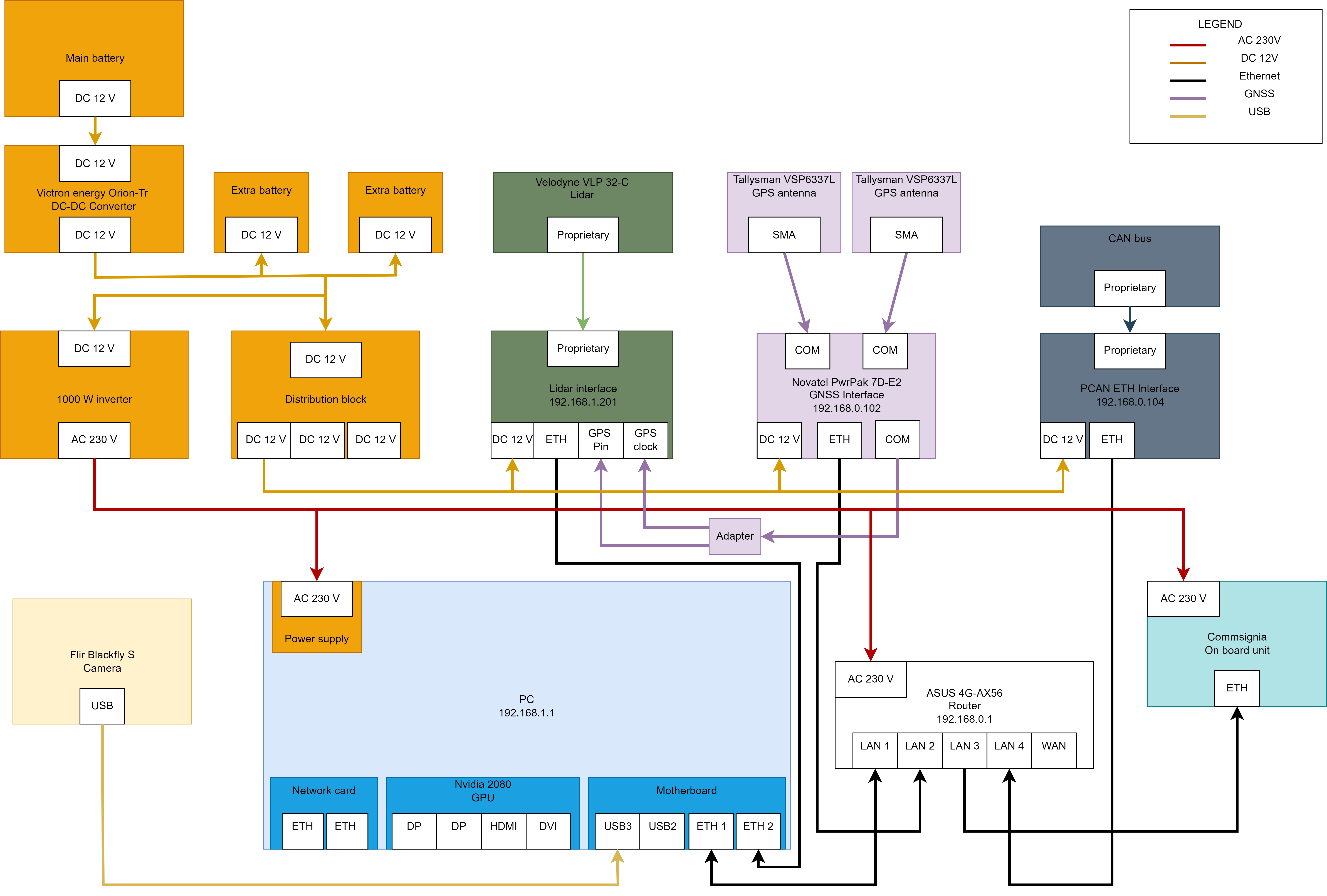
Different sensors and actuators connected to Henry are shown in the diagram below.
System
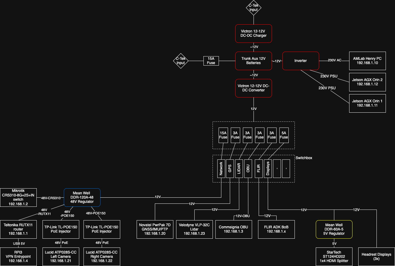
Power diagram
Signal diagram

CAN bus
The platform has access to 3 different high speed CAN networks. All the networks are presented below.
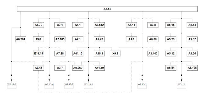
List of available control units in each network.
HS 1 CAN (C-1) (W2.13-1)
A1.1 Engine Control Unit
A3.440 Differential Control Unit (optional)
A3.8 Automatic Transmission Control Unit (optional)
A6.30 Central Electronics Control Unit
A7.14 Parking Aid Control Unit (optional)
A7.45 Media Interface Control Unit
X9.2 OBD Socket
HS 2 CAN (C-2) (W2.13-2)
A2.1 ABS Control Unit
A2.42 Vehicle Dynamics Control Unit
A4.1 Airbag Control Unit
A6.269 Image Processing Unit (optional)
A8.612 Headlamp Control Unit (optional)
A18.3 Selector Lever Control Unit
A41.10 Steering Booster Control Unit
A41.15 Steering Column Electronics Control Unit
X9.2 OBD Socket
HS 3 CAN (C-3) (W2.13-3)
A3.7 Cruise Control Unit (optional)
A6.269 Image Processing Unit (optional)
CAN bus connection to the vehicle is done via the gateway unit (at the same time gateway is providing the OBD socket) which is located under the steering wheel, behind OBD connector.

